 中文
中文
 English

Summary of Optical Fiber Fundamentals
Author:Dongguan Feifu Technology Co., Ltd
Click:
Time:2025-10-31 21:57:58
1. Concept of Optical Fiber
An optical fiber, abbreviated as fiber, is a slender strand made of glass or plastic that functions as a light transmission medium by leveraging the principle of total internal reflection for light propagation.
The ultra-thin optical fiber is encased in a plastic protective sheath, enabling it to bend without breaking. Typically, a transmitting device at one end of the fiber uses a light-emitting diode (LED) or a laser beam to send light pulses into the fiber, while a receiving device at the other end employs a photosensitive component to detect these pulses. A cable containing optical fibers is referred to as an optical fiber cable (or fiber optic cable).
Optical fibers are ideal for long-distance information transmission for two key reasons: first, the signal loss during light transmission through optical fibers is significantly lower than that of electrical signals traveling through wires; second, their primary raw material is silicon, which is abundant in nature and easy to extract, resulting in low production costs.
The primary application of optical fibers is communication. Currently, most communication-grade optical fibers are silica-based, composed mainly of high-purity fused silica, namely silicon dioxide (SiO₂).
An optical fiber communication system achieves communication by transmitting light waves that carry information through optical fibers.
2. Working Principle of Optical Fiber
The operating principle of an optical fiber is total internal reflection of light.
Optical Fiber Dispersion
Causes of DispersionAn optical signal transmitted through a fiber consists of multiple distinct components. Because different frequency components or mode components of the signal travel at varying speeds, a time delay difference arises between these components after propagation over a certain distance. This leads to waveform distortion and pulse broadening of the transmitted signal, a phenomenon known as optical fiber dispersion.
Impacts of DispersionThe presence of dispersion in optical fibers causes distortion and broadening of transmitted signal pulses, which in turn results in intersymbol interference (ISI). To ensure communication quality, the interval between symbols must be increased, which means lowering the signal transmission rate. This ultimately limits the communication capacity and transmission distance of the optical fiber system.
Classification of DispersionBased on their causes, optical fiber dispersion can be categorized into modal dispersion, material dispersion, waveguide dispersion, and polarization dispersion.
Optical Fiber Loss
Optical fiber loss refers to the reduction in optical power of a light signal after transmission through the fiber, caused by factors such as absorption and scattering.
Absorption Loss
- Intrinsic Absorption: The inherent absorption property of the fiber material itself.
- Impurity Absorption: The absorption of light by impurities present in the optical fiber.
Scattering LossIncludes linear scattering, nonlinear scattering, and scattering due to structural imperfections.
Other LossesSuch as microbending loss. Optical fibers are flexible and can be bent, but beyond a certain bending radius, although the fiber can still guide light, the light transmission path will change. This causes a conversion from guided modes to radiation modes, where part of the optical energy penetrates into the cladding or escapes through the cladding as radiation modes, resulting in power loss. When the bending radius is larger than 5–10 cm, the loss caused by bending is negligible.
3. Advantages of Optical Fiber Communication
- Huge Communication CapacityTheoretically, a single optical fiber can transmit 10 billion voice channels simultaneously. At present, tests for simultaneous transmission of 500,000 voice channels have been successfully completed, which is thousands to hundreds of thousands of times higher than that of traditional coaxial cables and microwave systems.
- Long Relay DistanceOptical fibers feature an extremely low attenuation coefficient. When equipped with appropriate optical transmitting/receiving equipment, optical amplifiers, forward error correction (FEC) and RZ coding modulation technologies, the relay distance can reach thousands of kilometers. By contrast, traditional cables can only transmit signals over 1.5 km and microwave systems over 50 km, which are simply incomparable.
- Excellent Confidentiality and Strong AdaptabilityOptical fiber communication is immune to external strong electromagnetic interference and resistant to corrosion.Since the core component of optical fibers is silica, they only transmit light signals without conducting electricity and are not affected by electromagnetic fields. Therefore, the optical signals transmitted through them are free from electromagnetic interference, giving optical fiber transmission strong resistance to electromagnetic and industrial interference. For the same reason, signals transmitted via optical fibers are not easily tapped, which facilitates secure communication.
- Small Size and Light WeightOptical fibers have the advantages of compact dimensions and low weight.
- Abundant Raw Material Sources and Low CostThe primary raw material for optical fibers is silica, which is widely available in nature and low in extraction cost.
Part 2: Types of Optical Fiber
4. Classification by Transmission Mode
Multimode Fiber (MMF)
It can transmit multiple modes of light. However, it suffers from high intermodal dispersion, which limits the frequency of transmitted digital signals — and this limitation becomes more pronounced as the transmission distance increases.
Single-mode Fiber (SMF)
It can only transmit a single mode of light, resulting in negligible intermodal dispersion. Therefore, it is suitable for long-distance communication.
Comparison Between Multimode and Single-mode Fiber
| Comparison Item | Multimode Fiber | Single-mode Fiber |
|---|---|---|
| Fiber Cost | Expensive | Less Expensive |
| Transmission Equipment | Basic, Low Cost | More Expensive (Laser Diodes Required) |
| Attenuation | High | Low |
| Transmission Wavelength | 850nm – 1300nm | 1260nm – 1650nm |
| Handling & Connection | Larger Core Diameter, Easy to Handle | Complex Connection |
| Transmission Distance | Local Networks (< 2km) | Access Networks / Medium & Long-haul Networks (> 200km) |
| Bandwidth | Limited | Almost Unlimited |
| Conclusion | Higher Fiber Cost, but Relatively Low Network Deployment Cost | Higher Performance, but High Network Deployment Cost |
Applications of Multimode and Single-mode Fiber
According to the recommendations of the International Telecommunication Union Telecommunication Standardization Sector (ITU-T), communication optical fibers are divided into seven categories from G.651 to G.657. Among them, G.651 is multimode fiber, while G.652 to G.657 are single-mode fibers.
| ITU Standard | Fiber Type | Name | Applicable Scenarios |
|---|---|---|---|
| G.651 | Multimode | Multimode Fiber | Short-distance transmission at 850nm/1310nm wavelengths (Ethernet, Local Area Networks - LANs) |
| G.652 | Single-mode | Non-Dispersion-Shifted Single-mode Fiber | Transmission at 1310nm–1550nm wavelengths (access networks); conventional single-mode fiber. Suitable for Fiber-to-the-Home (FTTH), long-haul and metropolitan area networks. |
| G.653 | Single-mode | Dispersion-Shifted Fiber | Long-distance transmission at 1550nm wavelength (backbone networks, submarine cables). It is quickly becoming obsolete. |
| G.654 | Single-mode | Cutoff Wavelength-Shifted Fiber | Long-distance transmission at 1550nm wavelength (submarine cables, does not support Dense Wavelength Division Multiplexing - DWDM); 5G bearer networks. |
| G.655 | Single-mode | Non-Zero Dispersion-Shifted Fiber | Long-distance transmission at 1550nm wavelength (backbone networks, submarine cables, supports DWDM). It may only be used for long-haul line maintenance in the later stage. |
| G.656 | Single-mode | Low-Slope Non-Zero Dispersion-Shifted Fiber | A type of non-zero dispersion-shifted fiber with strict requirements on dispersion slope, ensuring transmission performance over a wider wavelength range in DWDM systems. Low mass production potential. |
| G.657 | Single-mode | Bend-Insensitive Fiber | A new product developed to meet the requirements of FTTx technology and assembly applications. Derived from G.652 fiber, G.657 is the latest fiber variety designed to achieve the goal of FTTH. It is more suitable for information transmission in FTTH scenarios and installation in narrow spaces such as indoor environments or buildings. |
5. Optical Fiber Patch Cord/Cable
Also known as an optical fiber connector, it is fitted with connectors at both ends. An optical fiber patch cord consists of one or several optical fibers of a specific length plus optical connectors. It serves as a jumper cable for the link between equipment and optical fiber cabling, and is generally used to connect optical transceivers and terminal boxes.
Single-mode Fiber Patch Cord
- Generally yellow in color, with blue connectors and protective sleeves.
- Suitable for long-distance transmission; a single-mode fiber cable can support a connection distance of up to 10 km.
Multi-mode Fiber Patch Cord
- Generally orange (or sometimes gray) in color, with beige or black connectors and protective sleeves.
- Designed for short-distance transmission; the connection distance of a multi-mode fiber cable is much shorter, typically 300 m or 500 m. This variation mainly depends on the laser type: there are two common light sources emitting short-wavelength lasers, corresponding to the 62.5 μm and 50 μm core diameter specifications respectively.
Multi-mode fiber is usually cost-effective for use within buildings or corporate campuses, while single-mode fiber is more suitable for long-haul applications. Single-mode fiber can transmit signals over longer distances but generally requires more expensive supporting equipment. For installations with a length of no more than several hundred meters, multi-mode fiber offers a cost-efficient solution.
Common Types of Optical Fiber Interfaces
Optical fiber connectors are classified by the structure of their connectors into types including FC, SC, ST, LC, D4, DIN, MU, and MT-R. The most commonly used types are FC, SC, ST, and LC.
- FC Interface: Short for Ferrule Connector, it was first applied in storage area networks (SANs). It features a metal housing and a threaded interface, which ensures a secure and stable connection with optical modules.
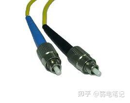
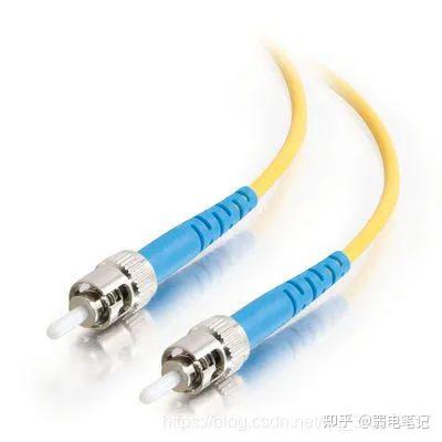
ST Interface:Short for Stab & Twist, it features a metal housing and a bayonet-style locking mechanism. It is commonly used in fiber optic distribution frames.
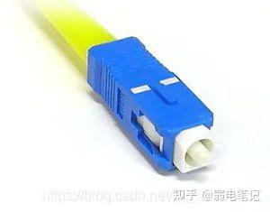
SC Interface:Short for Square Connector, it has a plastic housing and adopts a push-pull connection mechanism. The interface can be securely locked onto optical modules, and it is commonly used in switches.
The SC connector is a standard square-type connector made of engineering plastics, which offers the advantages of high temperature resistance and anti-oxidation. SC connectors are generally used for optical interfaces on the transmission equipment side.
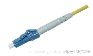
LC Interface:Short for Lucent Connector, it has a plastic housing and is designed for connecting to SFP optical modules, with the interface being securely lockable onto the modules.
The LC connector is similar in shape to the SC connector but smaller in size. By contrast, the FC connector features a metal housing and is generally used on the ODF (Optical Distribution Frame) side. Metal connectors allow a higher number of insertion and extraction cycles compared to plastic ones. In the labeling of pigtail connectors, designations such as FC/PC and SC/PC are commonly seen.
6. Optical Fiber Pigtail
Also referred to as a pigtail fiber or tail cord, it has a connector on one end and a cleaved fiber core of a cable on the other. It is primarily used to connect optical cables to fiber transceivers (with couplers, patch cords and other components required in between). Pigtails are generally housed inside fiber optic terminal boxes, and are joined to the cores of other optical cables via fusion splicing, which simplifies the installation and maintenance of fiber optic cable systems.
Classification of Optical Fiber Pigtails
Like optical fiber patch cords, pigtails are also categorized into single-mode pigtails and multimode pigtails, which differ in color, operating wavelength and transmission distance:
- Multimode pigtails: Typically orange in color, with an operating wavelength of 850 nm and a transmission distance of around 500 m.
- Single-mode pigtails: Typically yellow in color, with operating wavelengths of 1310 nm or 1550 nm, and a longer transmission distance ranging from 10 km to 40 km.
In addition, based on the number of fiber cores, pigtails can be further divided into single-core, 4-core, 6-core, 8-core, 12-core, 24-core pigtails and so on.
Functions of Optical Fiber Pigtails
The primary function of a pigtail is connection. When an optical cable is connected to a pigtail, the bare fiber core in the cable is fusion-spliced with the pigtail to form an integrated unit. The pigtail, with its individual fiber connector, is then connected to a fiber transceiver, bridging the optical fiber and twisted-pair cable to link to an information outlet.
Key tools used in the fiber fusion splicing process include: optical terminal boxes, fiber transceivers, pigtails, couplers, specialized fiber strippers, and fiber cleavers. The most commonly used pigtails in transmission systems feature five interface types: SC/PC, FC/PC, LC/PC, E2000/APC, and ST/PC.
Common Types of Optical Fiber Pigtails
- FC-SC Pigtail: Commonly known as a round-to-square pigtail. The FC end connects to an ODF (Optical Distribution Frame), while the SC end connects to the optical port of a device. This type of fiber connector was widely used in early SBS and Optix equipment.
- FC-FC Pigtail: Commonly known as a round-to-round pigtail. It is generally used as a jumper between ODF racks.
- SC-SC Pigtail: Commonly known as a square-to-square pigtail. It is typically used for connecting the optical line cards between devices.
- SC-LC Pigtail: The LC interface is commonly referred to as a small square connector pigtail, which is a snap-on type connector. Currently, this fiber connector is adopted in Huawei OSN series equipment, ZTE S series equipment, as well as early Lucent wavelength division multiplexing (WDM) equipment.
- LC-LC Pigtail: It is generally used for internal fiber connections between wavelength division multiplexing (WDM) devices, and has a relatively narrow range of applications.
7. MPO (Multi-fiber Push On) Optical Cable
Compared with other connectors, the most prominent features of MPO connectors are their compact design and high fiber count density. An MPO connector has the same physical dimensions as an SC connector but can accommodate 12 or 24 optical fibers, thus significantly saving wiring space in equipment cabinets. Currently, MPO connectors are available in configurations of 8, 12, 24, 48, 72, and 144 fibers, with 12-fiber and 24-fiber MPO patch cords being the most common. Specifically, 40G MPO-MPO patch cords typically adopt 12-fiber MPO multimode ferrules, while 100G MPO-MPO patch cords generally use 24-fiber MPO ferrules.
MPO connectors are primarily used with multimode optical fibers. According to the ISO 11801 standard, multimode optical cables are classified into OM1, OM2, OM3, OM4, and the newly released OM5 fibers.
OM stands for optical multi-mode, a standard used to grade multimode fibers. Fibers of different grades vary in transmission bandwidth and maximum reach.
- OM1: Supports Ethernet transmission up to 1 Gb/s.
- OM3 & OM4: Commonly deployed in data center cabling environments, supporting high-speed Ethernet transmission at 10G/40G/100G rates.
- OM5: Expands the bandwidth channel based on OM4, providing a solution for 100 Gb/s and 400 Gb/s wavelength transmission. OM5 fibers offer three key advantages:
- Exceptional Scalability: OM5 patch cords integrate short-wave wavelength division multiplexing (SWDM) and parallel transmission technologies, and can support 200/400G Ethernet applications with only 8 fibers of wideband multimode fiber.
- Effective Reduction of Construction and Operational Costs: Drawing on the wavelength division multiplexing (WDM) technology of single-mode fibers, OM5 patch cords extend the usable wavelength range for network transmission, enabling support for 4 wavelengths over a single multimode fiber, which greatly reduces network cabling costs.
- Outstanding Compatibility and Interoperability: OM5 fibers support legacy applications just like OM3 and OM4 patch cords, achieving full compatibility and high interoperability with traditional OM3 and OM4 patch cords. In the 400G era, OM5 multimode fibers boast broad application prospects and deliver excellent performance even during the upgrade of low-rate equipment to high-rate devices.
The next section will provide a detailed comparison of these fibers in terms of core size, bandwidth, data rate, transmission distance, color coding, and light source compatibility.
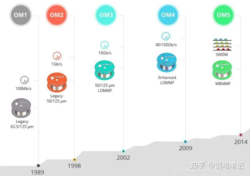
OM Fiber Specifications and Features
OM1 CableIt typically comes with an orange jacket and has a core diameter of 62.5 micrometers (µm). It can support 10 GbE transmission over distances up to 33 meters, and is most commonly used for 100 Mbps Ethernet applications.
OM2 CableIts recommended jacket color is orange. With a 50 µm core diameter (instead of 62.5 µm), it supports 10 GbE transmission up to 82 meters, but is more widely deployed in 1 GbE applications.
Both OM1 and OM2 are compatible with LED-based devices, which transmit light in hundreds of modes along the cable.
OM3 CableThe recommended jacket color is aqua blue. Like OM2, it features a 50 µm core diameter, but is optimized for laser-based devices that operate with fewer optical modes. As a result of this optimization, it can support 10 GbE transmission over distances up to 300 meters. Since its launch, manufacturing advancements have enhanced the overall performance of OM3, enabling it to support 100 GbE over distances of up to 40 meters and 100 meters respectively. Its most common application remains 10 GbE.
OM4 CableIt is fully backward compatible with OM3 fibers and shares the same distinctive aqua blue jacket. OM4 is specifically designed for VCSEL laser transmission. It supports 10 Gb/s link distances of up to 550 meters, compared to OM3’s 300 meters. When paired with MPO connectors, it can support 40/100 GbE transmission over distances up to 150 meters.
OM4 fibers are commonly used with transceivers such as 40G-SR4-OSFP+ and 100GBASE-SR4-OSFP28.
OM5 CableAlso known as WBMMF (Wideband Multimode Fiber), it is the latest generation of multimode fiber and is backward compatible with OM4. It has the same core diameter as OM2, OM3, and OM4, with a recommended jacket color of lime green. It is designed and specified to support at least four WDM channels in the 850–953 nm window, with a minimum speed of 28 Gbps per channel.
OM5 fibers can support 40G SWDM4 networks over distances up to 440 meters and 100G SWDM4 networks up to 150 meters.If data centers use non-IEEE standard 100G-SWDM4 transceivers, OM5 can support a transmission distance of 150 meters — only 50 meters longer than OM4.However, its cabling cost is approximately 50% higher than that of OM4.
Key Features of OM5
- Fewer Fibers for Higher Bandwidth ApplicationsOM5 patch cords operate at wavelengths of 850/1300 nm and support at least four wavelengths, while OM3 and OM4 typically operate at 850 nm and 1300 nm. In other words, traditional OM1, OM2, OM3, and OM4 multimode fibers only offer a single channel, whereas OM5 provides four channels, quadrupling the transmission capacity. By combining Short-Wave Wavelength Division Multiplexing (SWDM) and parallel transmission technologies, OM5 only requires 8 fibers of WBMMF to support 200/400 GbE applications. This significantly reduces the fiber count and cuts down network cabling costs substantially.
- Longer Transmission DistanceOM5 offers longer transmission distances than OM3 and OM4. OM4 is designed to support 100G-SWDM4 transceivers over distances of at least 100 meters, while OM5 can support the same transceivers over distances up to 150 meters.
- Lower Fiber AttenuationThe attenuation of OM5 WBMMF is reduced from 3.5 dB/km (typical of OM3 and OM4) to 3.0 dB/km. Additionally, it has enhanced bandwidth requirements at the 953 nm wavelength.OM5 has the same fiber dimensions as OM3 and OM4, meaning it is fully compatible with them. There is no need to modify existing cabling infrastructure to deploy OM5. With superior scalability and flexibility, OM5 can support higher-speed network transmission with fewer multimode fibers, while its cost and power consumption are far lower than those of single-mode fibers. Therefore, it is expected to be widely adopted in 100G/400G/1T hyperscale data centers in the future.
Summary of OM Fiber Applications
- OM1 and OM2 have been widely deployed for in-building applications for many years, supporting Ethernet transmission up to 1 Gb/s.
- OM3 and OM4 cables are typically used in data center cabling environments, supporting high-speed Ethernet transmission at 10 Gb/s and even 40/100 Gb/s.
- OM5 is designed for 40 Gb/s and 100 Gb/s transmission, and can reduce the number of fibers required for high-speed transmission.
物理方面差异:
物理差异主要在于直径,护套颜色,光源和带宽,如下表所述。
| MMF电缆类型 | 直径 | 外套颜色 | 光源 | 带宽 |
|---|---|---|---|---|
| OM1 | 62.5 / 125微米 | 橙子 | 发光二极管 | 200MHz *公里 |
| OM2 | 50/125微米 | 橙子 | 发光二极管 | 500MHz *公里 |
| OM3 | 50/125微米 | 水蓝色 | VSCEL | 2000MHz *公里 |
| OM4 | 50/125微米 | 水蓝色 | VSCEL | 4700MHz *公里 |
| OM5 | 50/125微米 | 水绿色 | VSCEL | 28000MHz *公里 |
实际差异:
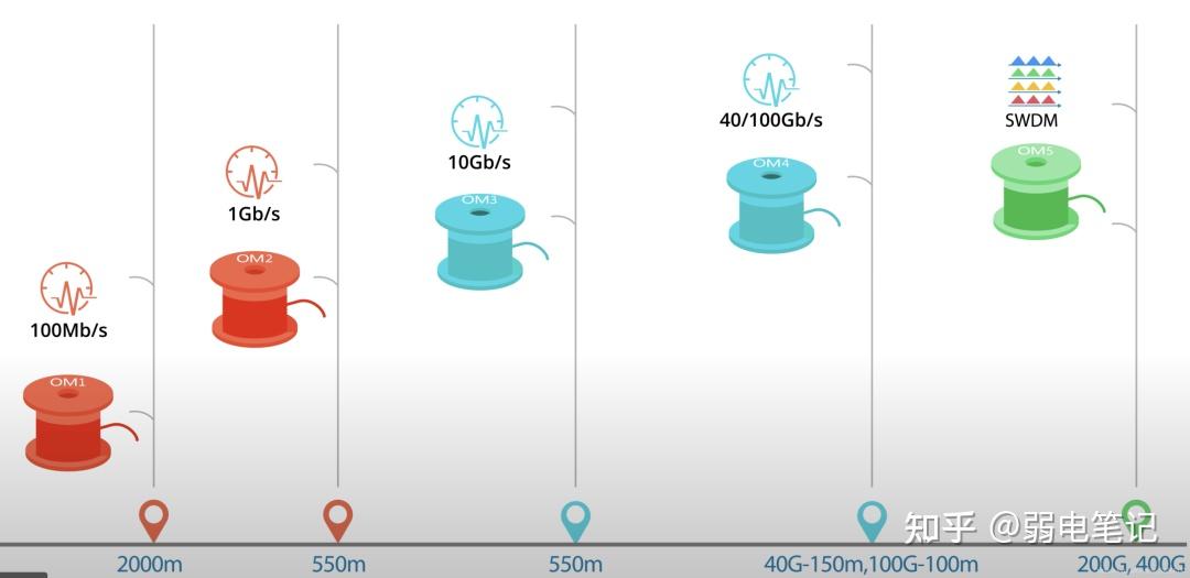
多模光纤能够以各种数据速率传输不同的距离范围。可以根据实际应用选择最合适的一种。下面指定了不同数据速率下的最大多模光纤距离比较。
| MMF类别 | 快速以太网 | 1GbE | 10GbE | 40GbE | 100GbE |
|---|---|---|---|---|---|
| OM1 | 2000m | 275m | 33m | / | / |
| OM2 | 2000m | 550m | 82m | / | / |
| OM3 | 2000m | / | 300m | 100m | 70m |
| OM4 | 2000m | / | 550m | 150m | 150m |
| OM5 | / | / | 550m | 150m | 150m |
Physical Differences
Physical variations are mainly reflected in core diameter, jacket color, light source, and bandwidth, as detailed in the table below.
| MMF Cable Type | Core Diameter | Jacket Color | Light Source | Bandwidth |
|---|---|---|---|---|
| OM1 | 62.5/125 µm | Orange | Light-Emitting Diode (LED) | 200 MHz·km |
| OM2 | 50/125 µm | Orange | Light-Emitting Diode (LED) | 500 MHz·km |
| OM3 | 50/125 µm | Aqua Blue | VCSEL | 2000 MHz·km |
| OM4 | 50/125 µm | Aqua Blue | VCSEL | 4700 MHz·km |
| OM5 | 50/125 µm | Lime Green | VCSEL | 28000 MHz·km |
Practical Performance Differences
Multimode fibers can transmit signals over varying distances at different data rates. The optimal type can be selected based on actual application scenarios. The table below specifies the maximum transmission distances of multimode fibers at different data rates.
| MMF Category | Fast Ethernet | 1GbE | 10GbE | 40GbE | 100GbE |
|---|---|---|---|---|---|
| OM1 | 2000 m | 275 m | 33 m | / | / |
| OM2 | 2000 m | 550 m | 82 m | / | / |
| OM3 | 2000 m | / | 300 m | 100 m | 70 m |
| OM4 | 2000 m | / | 550 m | 150 m | 150 m |
| OM5 | / | / | 550 m | 150 m | 150 m |
Differences Between MPO and MTP
MPO (Multi-fiber Push On) is the first-generation spring-loaded multi-fiber connector designed by Japan’s NTT Communications. It is now a generic name for multi-fiber connectors manufactured by several companies.MTP® (Multi-Fiber Pull Off) is a registered brand owned by US Conec, referring specifically to its proprietary type of MPO-compatible connectors.
Therefore, MTP® connectors are fully compatible with all standard MPO connectors and can be directly interconnected with other MPO-based infrastructure. However, compared with generic MPO connectors, MTP® connectors incorporate multiple engineered enhancements to deliver superior mechanical and optical performance.
The core difference between MTP® and MPO optical cables lies in their connectors. As an upgraded version, MTP® cables equipped with MTP® connectors feature improved mechanical design and optical performance.
Key Features of MTP® Connectors
- Removable Housing ComponentsThe outer housing components of MTP® connectors can be easily removed, facilitating maintenance and reconfiguration.
- Reusable MT Ferrule DesignThe MT ferrule design ensures no performance degradation during production rework or re-polishing. The gender (male/female) of the connector can be flexibly changed even after assembly or on-site deployment, and the ferrule can pass interference testing post-assembly.
- Floating Ferrule for Enhanced AlignmentThe floating ferrule design of MTP® connectors improves transmission performance during mechanical mating. It allows the mating ferrules to maintain optimal physical contact even when subjected to external forces.
- Stainless Steel Oval Guide PinsMTP® connectors adopt stainless steel oval guide pins, which enhance mating precision and reduce wear on guide holes, enabling MTP® connectors to maintain high-performance transmission over an extended service life.
- Integrated Metal Pin ClampA built-in metal pin clamp secures the push ring, providing three key benefits:
- Prevents loss of guide pins;
- Concentrates the pressure exerted by the spring;
- Avoids spring contact or friction with optical fibers during mechanical expansion/contraction, thus preventing fiber damage.
- Optimized Spring Design for Ribbon FibersThe spring design of MTP® connectors maximizes the ribbon gap for 12-fiber and multi-fiber ribbon applications, preventing fiber damage.
- Versatile Adapter CompatibilityMTP® connectors offer at least four standard adapter options to accommodate different cable types, enhancing practicality:
- Loose-tube round cables;
- Ribbon cables with elliptical jackets;
- Bare ribbon fibers;
- Ultra-short boot connector components, ideal for space-constrained installations, reducing volume by 45%.
8. AOC (Active Optical Cable)
AOC is the abbreviation of Active Optical Cable. It refers to an integrated active optical cable that combines optical transceivers and optical fibers, featuring simple and convenient operation.
An AOC integrates two optical transceivers and an optical cable into a single package. Since the transmission medium in between is optical fiber, the transceivers in an AOC are equipped with laser devices, resulting in a higher cost compared to DACs. However, its optical ports are not exposed, which ensures extremely high reliability. Another advantage is that its operating distance can be customized for long-reach applications within 100 meters.
In essence, an AOC is an optical fiber patch cord with built-in optical transceivers. AOCs are generally available in short lengths, up to a few hundred meters at most. Their most distinctive feature is that the optical transceivers and fibers are integrated into an inseparable unit.
This integrated design helps reduce the overall cost, as fixing the fibers inside the transceivers eliminates the need for certain optical components during manufacturing. AOCs are suitable for short-distance application scenarios but not for long-haul transmission — this is obvious, as optical cables cannot be made infinitely long. AOCs are widely deployed in IDC (Internet Data Center) server rooms.
Advantages of AOCs:
Low environmental requirements, with no need for cleaning optical fiber connectors.
Cost-optimized design, and they do not come with DDM (Digital Diagnostic Monitoring) functionality.
Disadvantages of AOCs:
Inflexible distance configuration — the transmission distance must be confirmed in advance before factory shipment.
Comparison Between AOC and DAC
DAC, short for Direct Attach Cable, is simply a cable fitted with optical transceivers at both ends. It is widely used in storage area networks, data centers, and high-performance computing connections, and is gradually gaining traction in network communications. Specifically, DACs are constructed with silver-plated conductors and foamed insulated cores, adopting pair-wise shielding and overall shielding to achieve high-speed signal transmission.
Advantages of DACs:
High Interchangeability: With the advancement of copper cable technology, DACs are interchangeable and hot-swappable with fiber optic transceivers.
Low Cost: Copper cables are cheaper than optical fibers, so using DACs helps reduce cabling costs.
Excellent Heat Dissipation: DACs are made of copper cores, which offer good heat dissipation performance.
Disadvantages of DACs:
Short transmission distance, heavy weight, large volume, difficult management, and susceptibility to electromagnetic interference — which may cause issues such as signal malfunction and degradation.
The main disadvantage of AOCs, by contrast, is their relatively high cost.
9. Differences Between Optical Fiber and Optical Fiber Cable
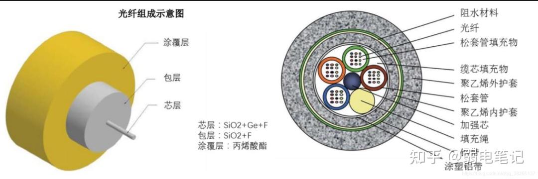
An optical fiber is a thin, flexible medium designed to transmit light beams. Most optical fibers must be covered with multiple layers of protective structures before use; the enclosed cable is then defined as an optical fiber cable. In other words, the optical fiber serves as the core component of the cable, and an optical fiber cable is formed by encasing the fiber with protective components and auxiliary layers.
The outer protective structure of the optical fiber prevents damage from the surrounding environment. An optical fiber cable consists of three main parts: optical fiber, buffer layer, and outer sheath. Similar to a coaxial cable, an optical fiber has no mesh shielding layer; its center is a glass core through which light propagates.
Optical fibers are usually bundled together and protected by an outer casing. The fiber core is typically a double-layer concentric cylinder made of fused silica, with a very small cross-sectional area. It is brittle and prone to breakage, hence the need for an additional protective layer. This is the fundamental distinction between optical fiber and optical fiber cable.
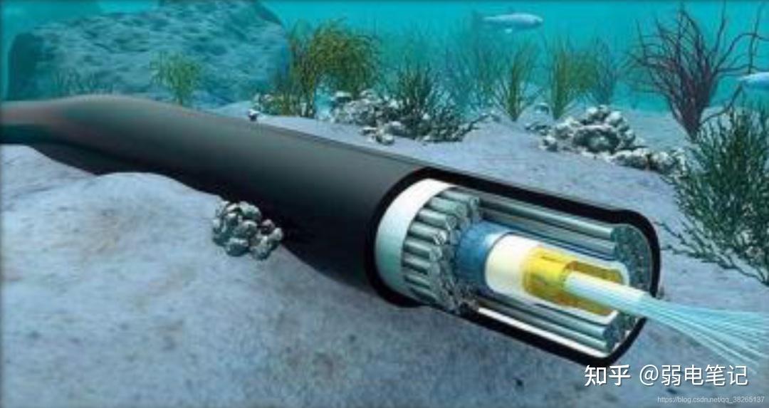
Submarine Optical Fiber Cable
Submarine optical fiber cables are an effective means of achieving international information interconnection and transmission, playing a pivotal role in global communications. With the rapid development of cloud computing, big data, the Internet of Things and other industries, global data exchange and connection have become an urgent necessity. The demand for interconnection between global IDCs, as well as for communication and network interconnection, has boosted the demand for international optical cables.
Submarine optical fiber cables have emerged as the primary form of international optical cables, thanks to their advantages of high quality, high definition, large capacity, excellent security performance, and high cost-effectiveness. According to TeleGeography, currently more than 95% of cross-border data transmission worldwide is carried out via submarine optical fiber cables. Submarine optical fiber cables outperform satellite communication and other technical means in terms of transmission capacity and cost-effectiveness, making them the most important intercontinental communication technology at present.
The core of a submarine optical fiber cable is made of high-purity optical fibers, which guide light along the fiber path through total internal reflection. The manufacturing process of a submarine optical fiber cable involves the following steps:
- First, the optical fibers are embedded in a jelly-like compound to protect the cable from damage even when in contact with seawater.
- Then, the fiber bundle is enclosed in a steel tube to withstand underwater pressure.
- Next, the steel tube is wrapped in high-strength steel wires and enclosed in a copper tube for further protection.
- Finally, an outer sheath made of polyethylene is applied to complete the cable structure.
Part 3: Major Manufacturers in the Optical Fiber Industry
In the global optical fiber and cable rankings, the top 10 enterprises are divided among 4 countries: the United States (Corning), Italy (Prysmian), Japan (Furukawa Electric/OFS, Sumitomo Electric, Fujikura), and China (Yangtze Optical Fibre and Cable, Hengtong Optic-Electric, FiberHome Telecommunication, Futong Group, Zhongtian Technology). Chinese enterprises hold half of the market share. Three Chinese companies — Yangtze Optical Fibre and Cable, Hengtong Optic-Electric, and FiberHome Telecommunication — account for a considerable market share.
Yangtze Optical Fibre and Cable ranks 2nd globally with a 12% market share, while Hengtong Optic-Electric takes the 3rd place with 11%. FiberHome Telecommunication, Futong Group, and Zhongtian Technology rank 5th, 6th, and 9th with 7%, 8%, and 8% market shares respectively. The respective market shares of other international players are: Corning 15%, Furukawa/OFS 10%, Sumitomo Electric 5%, Prysmian 6%, and Fujikura 4%.
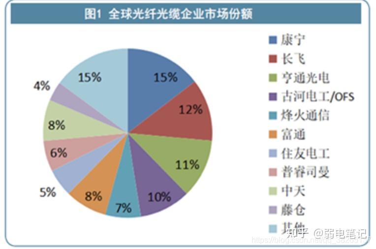
Diagram: Global Optical Fiber and Cable Enterprise Market Share in 2019
10. Major International Manufacturers
- Corning: Its optical fiber manufacturing plant in Wilmington, North Carolina, USA, is the world’s first optical fiber production facility and remains one of the largest optical fiber manufacturers globally.
- Furukawa Electric: Headquartered in Tokyo, Japan, it is a large multinational corporation.
- Prysmian: Headquartered in Milan, Italy, it is a world leader in the energy and communication cable systems industry.
- Sumitomo Electric: It is Japan’s leading cable producer, and together with Furukawa Electric and Fujikura, it is known as the 'Big Three of Electric Wires' in Japan.
- Fujikura: Its business scope covers comprehensive cable products.
11. Major Domestic Manufacturers (China)
- Yangtze Optical Fibre and Cable: Based in Wuhan, Hubei, it ranks first in domestic optical fiber preform production capacity with strong R&D capabilities, accounting for over 30% of China’s total preform output. It is also the only domestic enterprise with the capability to export optical fiber preforms.
- Hengtong Optic-Electric: Headquartered in Suzhou, Jiangsu, it has a dual layout in optical fiber and optical modules, and seizes opportunities in marine communication.
- Zhongtian Technology: Located in Jiangsu, it has a multi-dimensional layout of 'cloud, pipe, terminal' and independently developed G.654 optical fiber technology.
- FiberHome Telecommunication: Based in Wuhan, Hubei, it advances hand in hand in optical communication and ICT (Information and Communications Technology) businesses.
- Tongding Interconnect: Headquartered in Suzhou, Jiangsu, it has basically formed an integrated advantage in the optical fiber and cable, and optical preform sectors. It has the production capacity of the entire industrial chain of communication cables, including optical fiber preforms, optical fibers, optical cables, communication cables, and power cables.
- Futong Cable: Based in Shenzhen, it mainly produces and sells optical fibers, optical cables, and semi-finished products, and provides manufacturing and processing services for related supporting products, components, and raw materials.
Part 4: Main Causes of Optical Fiber Failures
12. Causes of Optical Fiber Failures
- Excessively Long Optical Cable
- Excessive Bending
- Cable Compression or Fracture: Optical fibers are subject to uneven stress, e.g., external pressure or micro-irregular bending and even fracture of the fiber axis caused by temperature changes in the coated fiber. This results in the conversion of guided modes into radiation modes, leading to optical power loss.
- Poor Fusion Splicing of Cables
- Core Diameter Mismatch
- Filler Diameter Mismatch
- Connector Contamination: Contamination of optical fiber connectors and moisture absorption of pigtails are among the primary causes of optical cable communication failures.
- Poor Polishing at Connectors
- Poor Contact at Connectors: This issue mainly occurs at optical path terminals, such as optical distribution frames and optical switches. It may be caused by operator negligence, equipment quality defects, or connector aging, leading to loose fiber connections, which results in reflective loss and leakage attenuation of optical signals.
